How to Draw Mcnabbs Line on Lymbar Xray
Measurements in Skeletal Radiology
Lindsay J. Rowe
Terry R. Yochum
INTRODUCTION
Since the time of the first roentgen image, measurements have been used to evaluate normal and abnormal skeletal relationships. Many measurements have been determined through astute observation and appropriate statistical evaluation.
In all analytical assessments of skeletal spatial relationships, the outcome depends on the quality of the radiographic data collected and on its correct interpretation. Any attempt to measure and quantify the human frame has inherent uncontrolled error. The major errors arising in the mensuration process include (a) image unsharpness, (b) projectional geometric distortion, (c) inconsistency in patient positioning, (d) individual anatomic variation, (e) imprecision in locating standard reference points, and (f) observer error. (1,2,3,4)
Additional confusion exists around the issues of clinical interpretation of measurements and their application to treatment protocols. This is highlighted in the spine and pelvis, where small measurements derived from various systems of analysis have often exerted a strong influence on treatment regimes. Among the various systems of analysis there appears to be little correlation in the results obtained. (1,5,6,7) Many measurements have been used to evaluate spinal segmental motion abnormalities from static radiographs, which inadequately reflect motion biomechanics.
In general, any measurement is meaningless unless it is performed accurately and correlated clinically. (8,9) Too often it is the x-ray that is treated, not the patient. To rely on a radiographic measurement as the sole criterion for a particular treatment method is a frail approach to patient care.
In this chapter each measurement is described according to synonyms, optimum projections, landmark reference points, normal values, special considerations, and significance. Whenever numerical data are given, they have been rounded for simplicity. Unless otherwise stated, the measurements are film image sizes and are not corrected for true anatomic dimensions. References to the literature are included so the reader may seek further information.
CORRECTION OF GEOMETRIC DISTORTION
Numerous methods can be used to determine the anatomic dimensions demonstrated on a given radiograph. These include nomograms and algebraic formulations. (1,2) The roentgen image is always larger than the true anatomic size because of the effect of diverging rays on a structure not in close contact with the film.
To algebraically arrive at the correct object size (O), three values must be known: (Fig. 2-1)
-
Film image dimension (cm) (I)
-
Target film distance (cm) (D)
-
Object film distance (cm) (d)
Initially, a correction factor (CF) is calculated:
![]()
The film image dimension (I) is then multiplied by this correction factor:
O = I × CF
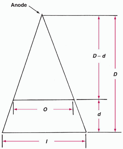
Figure 2-1 GEOMETRIC DISTORTION IN IMAGE PRODUCTION.
SKULL
Vastine-Kinney Method of Pineal Gland Localization
Technique
Projection.
Lateral skull.
Landmarks.
The pineal gland must be visible as a result of calcium deposition before the following four measurements are made: (1) (Fig. 2-2)
-
The greatest distance from the pineal gland to the inner table of the frontal bone
-
The greatest distance from the pineal gland to the inner aspect of the occipital bone
-
The greatest distance from the pineal gland to the inner table of the skull vertex
-
The greatest distance from the pineal gland to the posterior margin of the foramen magnum
Normal Measurements.
Measurements A and B are used to assess anterior or posterior pineal displacement, whereas measurements C and D are used to assess superior or inferior displacement.
-
Anteroposterior (AP) position. Measurement A is plotted against the sum of A and B and should fall within the specified range.
-
Superoinferior position. Measurement C is plotted against the sum of C and D and also should fall within a specified range. (2)
Special Considerations.
An alternative and more accurate method for pineal gland localization is the Pawl-Walter method. (3)
Significance.
A pineal shift may be caused by a space-occupying mass, such as a tumor, hemorrhage, or localized atrophic cerebral disease. The most accurate means by which to locate the pineal gland is the MRI scan.
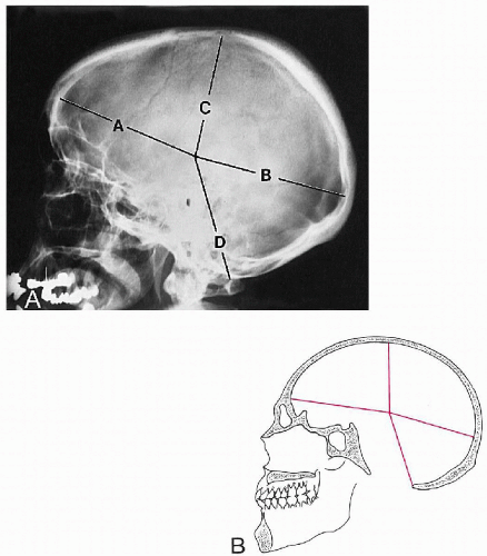
Figure 2-2 VASTINE-KINNEY METHOD OF PINEAL LOCALIZATION. A and B. See text.
Sella Turcica Size
Synonyms.
Pituitary fossa size.
Technique
Projection.
Lateral skull.
Landmarks.
Two measurements are made: the greatest AP diameter and the greatest vertical diameter. The AP value is the widest distance between the anterior and posterior surfaces of the pituitary fossa. The vertical dimension is between the fossa floor and the plane between the opposing surfaces of the anterior and posterior clinoid processes. (4,5) (Fig. 2-3)
Normal Measurements.
The AP dimension averages about 11 mm, with a normal range of 5-16 mm. The vertical measurement averages about 8 mm, with a normal range of 4-12 mm. (4,5,6) (Table 2-1) In children these values will be progressively smaller with decreasing chronologic age.
| Table 2-1 Normal Values for Sella Turcica Size | ||||||||||||
|---|---|---|---|---|---|---|---|---|---|---|---|---|
|
Special Considerations.
All lateral flexion and rotation of the skull should be eliminated for these measurements to be accurate.
Significance.
The finding of a small sella is of debatable significance. (7) However, an enlarged sella may be associated with a pituitary neoplasm, empty sella syndrome, or extrapituitary mass (neoplasm, aneurysm); it may even be a normal variant.
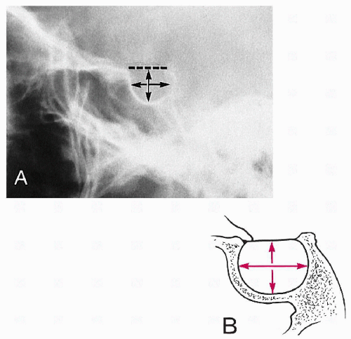
Figure 2-3 LATERAL MEASUREMENTS OF THE SELLA TURCICA. A and B. See text.
Basilar Angle
Synonyms.
Welcker's basilar angle, Martin's basilar angle, sphenobasilar angle.
Technique
Projection.
Lateral skull.
Landmarks.
Three points are located and joined together by two lines; the subsequent angle is measured. The three points are the nasion (frontal-nasal junction), the center of the sella turcica (midpoint between the clinoid processes), and the basion (anterior margin of the foramen magnum). (Fig. 2-4)
Normal Measurements.
The average normal angle subtended by these two lines is 137°, with a normal variation of 123-152°. (8) (Table 2-2)
| Table 2-2 Normal Values for Basilar Angle | ||||||
|---|---|---|---|---|---|---|
|
Special Considerations.
None.
Significance.
The measurement is an index of the relationship between the anterior skull and its base. The angle will increase beyond 152° in platybasia, in which the base is elevated in relation to the rest of the skull. This may or may not be associated with basilar impression. The deformity may be congenital (isolated impression, occipitalization) or acquired (Paget's disease, rheumatoid arthritis, fibrous dysplasia).
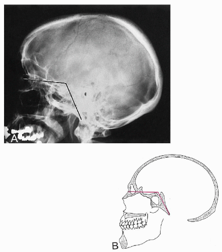
Figure 2-4 BASILAR ANGLE. A and B. See text.
McGregor's Line
Technique
Projection.
Lateral skull; lateral cervical spine.
Landmarks.
A line is drawn from the posterosuperior margin of the hard palate to the most inferior surface of the occipital bone. (9) The relationship of the odontoid apex to this line is then examined. (Fig. 2-5)
Normal Measurements.
In 90% of individuals the odontoid apex should not lie above this line > 8 mm in males and > 10 mm in females. (9) In children younger than 18 years, these maximum values diminish with decreasing chronologic age.
Special Considerations.
Of all methods used to evaluate for basilar impression on the lateral projection, McGregor's line appears to be the most accurate and reproducible. (10)
Significance.
An abnormal superior position of the odontoid indicates basilar impression. Common precipitating causes include platybasia, atlas occipitalization, and bone-softening diseases of the skull base (e.g., Paget's disease, osteomalacia, and fibrous dysplasia). Occasionally, rheumatoid arthritis may also precipitate this deformity.
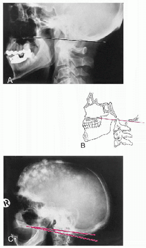
Figure 2-5 MCGREGOR'S LINE. A and B. Normal Line. See text. C. Abnormal Line. Note the tip of the odontoid (retouched) is well above the line owing to basilar invagination from Paget's disease.
Chamberlain's Line
Synonyms.
Palato-occipital line.
Technique
Projection.
Lateral skull; lateral cervical spine.
Landmarks.
A line is constructed from the posterior margin of the hard palate to the posterior aspect of the foramen magnum. The relationship of this line to the tip of the odontoid process is then assessed. (11) (Fig. 2-6)
Normal Measurements.
In the majority of patients the tip of the odontoid process should not project above this line; however, a normal variation of 3 mm above this line may occur. (8) A measurement of ≥7 mm is definitely abnormal.
Special Considerations.
This relationship can also be evaluated on lateral cervical views but is best done on lateral skull films, preferably with computed tomography (CT). To locate the posterior aspect of the foramen magnum, identify the inner table of the occipital bone, follow it anteriorly, and observe for an oblique cortical white line crossing the diploe to merge with the outer table. This should be found slightly posterior to the plane of the atlas spinolaminar junction.
Significance.
An abnormal superior position of the odontoid indicates basilar impression. Common precipitating causes include platybasia, atlas occipitalization, and bone-softening diseases of the skull base (e.g., Paget's disease, osteomalacia, and fibrous dysplasia). Occasionally, rheumatoid arthritis may also precipitate this deformity.
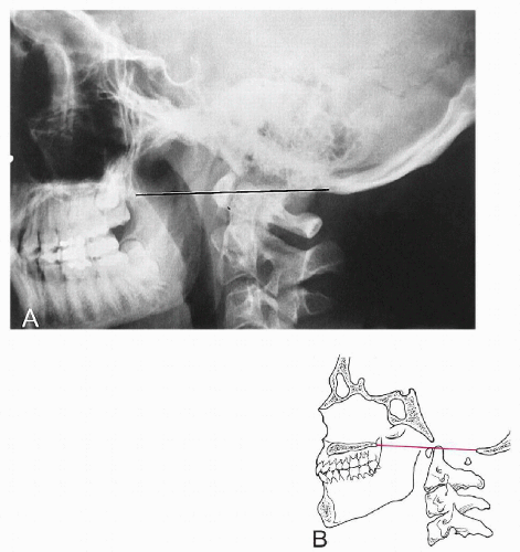
Figure 2-6 CHAMBERLAIN'S LINE. A and B. See text.
Macrae's Line
Synonyms.
Foramen magnum line.
Technique
Projection.
Lateral skull.
Landmarks.
A line is drawn between the anterior (basion) and posterior (opisthion) margins of the foramen magnum. Two assessments are then made in relation to this line: (a) the occipital bone and (b) the odontoid process. (Fig. 2-7)
Normal Measurements.
The inferior margin of the occipital bone should lie at or below this line. In addition a perpendicular line drawn through the odontoid apex should intersect this line in its anterior quarter. (10,12)
Special Considerations.
A true lateral view with no lateral flexion distortion should be obtained for this positional line to be applied.
Significance.
If the inferior margin of the occipital bone is convex in a superior direction and/or lies above this line, then basilar impression is present. Predisposing causes include platybasia, occipitalization, rheumatoid arthritis, and bone-softening diseases (e.g., Paget's disease, osteomalacia, and fibrous dysplasia). If the odontoid apex does not lie in the ventral quarter of this line, a dislocation of the atlanto-occipital joint or a fracture or dysplasia of the dens may be present.
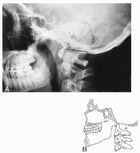
Figure 2-7 MACRAE'S LINE. A and B. See text.
Digastric Line
Technique
Projection.
AP open mouth.
Landmarks.
The digastric groove medial to the base of the mastoid process is located on each side and a line is drawn between them. The vertical distance to the odontoid apex and atlanto-occipital joints is then measured. (Fig. 2-8)
Normal Measurements.
The digastric line-odontoid apex measurement averages 11 mm but may range between 1 and 21 mm. The odontoid should not project above this line. The digastric line-atlanto-occipital joint average measurement is 12 mm, with a normal range between 4 and 20 mm. (10,13) (Table 2-3)
| Table 2-3 Normal Values for Digastric Line | ||||||||||||
|---|---|---|---|---|---|---|---|---|---|---|---|---|
|
Special Considerations.
Computed tomography (CT) evaluation is the most accurate method for obtaining clear visualization of the necessary anatomic landmarks.
Significance.
Both measurements will decrease in basilar impression owing to platybasia, occipitalization, and bone-softening diseases (e.g., Paget's disease, osteomalacia, and fibrous dysplasia).
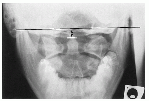
Figure 2-8 DIGASTRIC LINE. See text.
Height Index of Klaus
Technique
Projection.
Lateral skull; lateral cervical spine.
Landmarks.
A line is drawn from the tuberculum sellae to the internal occipital protuberance. The vertical distance between this line and the apex of the odontoid is measured. (14) (Fig. 2-9)
Normal Measurements.
See Table 2-4.
| Table 2-4 Normal Values for Height Index of Klaus | ||||
|---|---|---|---|---|
|
Special Considerations.
None.
Significance.
A measurement < 30 mm indicates basilar impression. Values between 30 and 36 mm reflect a tendency toward basilar impression. (10,14) The wide range of normal variation casts doubt on the usefulness of this measurement. (12)
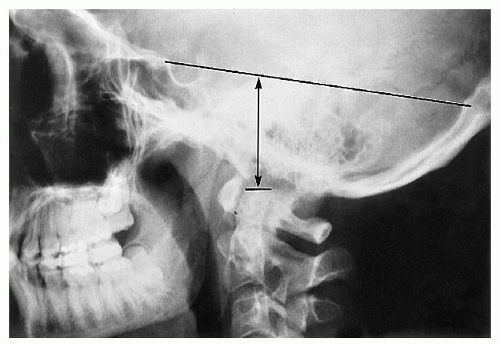
Figure 2-9 HEIGHT INDEX OF KLAUS. See text.
Boogard's Line and Angle
Technique
Projection.
Lateral skull; lateral cervical spine.
Landmarks.
-
Boogard's line. A line is drawn connecting the nasion to the opisthion. (15) (Fig. 2-10A)
-
Boogard's angle. (a) A line is drawn between the basion and the opisthion (Macrae's line). (b) A second line is drawn from the dorsum sellae to the basion along the plane of the clivus. (c) The angle between these two lines is measured. (15) (Fig. 2-10B)
Normal Measurements
-
Boogard's line. The basion should lie below this line.
-
Boogard's angle. See Table 2-5.
| Table 2-5 Normal Values for Boogard's Angle | ||||||
|---|---|---|---|---|---|---|
|
Special Considerations.
None.
Significance.
Both measurements will be altered in basilar impression—the basion will be above Boogard's line, and the angle will be > 135°.
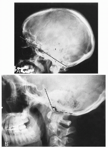
Figure 2-10 BOOGARD'S LINE AND ANGLE. A. Boogard's Line. See text. B. Boogard's Angle. See text.
Anterior Atlanto-Occipital Dislocation Measurement
Technique
Projection.
Lateral cervical spine; lateral skull.
Landmarks.
Four osseous landmarks are located: the basion, opisthion, and anterior and posterior arches of the atlas. Two measurements are then made: The first is the distance between the basion and the posterior arch at the spinolaminar junction (B-P), and the second is the distance between the opisthion and the posterior margin of the anterior arch (O-A). The ratio of these two measurements (B-P:O-A) is then calculated. (16) (Fig. 2-11)
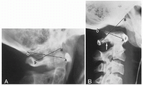
Figure 2-11 ATLANTO-OCCIPITAL RELATIONSHIP. A. Normal Relationship. B. Anterior Dislocation. See text. Observe the posterior arch fracture of C1 (arrow). (Courtesy of Steven B. Wasserman, DC, Long Beach, California.)
Normal Measurements.
In the normal individual the ratio is always < 1.
Special Considerations.
This relationship can be assessed only when there are no associated fractures or dislocations of the atlas and odontoid process.
Significance.
When the ratio is ≥1, then an anterior atlanto-occipital dislocation probably exists.
CERVICAL SPINE
Atlantodental Interspace (ADI)
Synonyms.
Atlas-odontoid space, predental interspace, atlas-dens interval.
Technique
Projection.
Lateral neutral; flexion-extension cervical spine.
Landmarks.
The distance measured is between the posterior margin of the anterior tubercle and the anterior surface of the odontoid. (Fig. 2-12)
Normal Measurements.
A small, insignificant difference exists between males and females. The measurement is slightly increased in normal children. (1,2) (Table 2-6) In flexion the shape of the interspace takes on a V configuration, whereas in extension it has an inverted V pattern. (3,4)
Special Considerations.
Flexion is the optimum view to assess the interspace, because in this position the most stress is placed on the transverse ligament of the atlas.
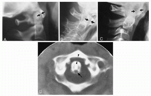
Figure 2-12 ATLANTODENTAL INTERSPACE. A. Normal Adult Interspace. The interspace measures < 3 mm (arrows). B. Abnormal Interspace. On flexion a patient with rheumatoid arthritis exhibits anterior translation of the atlas by 5 mm (arrows). C. Normal Childhood Interspace. The interspace measures < 5 mm (arrows). D. CT Scan, Abnormal Interspace. In this patient with rheumatoid arthritis, the atlantodental interspace is increased (arrowheads). Note the erosion at the posterior surface of the odontoid at the site of synovial tissue beneath the transverse ligament (arrow).
| Table 2-6 Normal Values for Atlantodental Interspace | |||||||||
|---|---|---|---|---|---|---|---|---|---|
|
Significance.
There are numerous disorders that may alter the interspace. A decreased space is to be expected with advancing age because of degenerative joint disease of the atlantodental joint. A more significant change is an abnormally widened space with reduction in the neural canal size. (5) The most frequent causes include trauma, occipitalization, Down's syndrome, pharyngeal infections (Grisel's disease), and inflammatory arthropathies (e.g., ankylosing spondylitis, rheumatoid arthritis, psoriatic arthritis, and Reiter's syndrome). (5,6)
Method of Bull
Technique
Projection.
Lateral skull; lateral cervical spine.
Landmarks.
Two lines are drawn and the resultant angle measured. The first line is drawn from the posterior aspect of the hard palate to the posterior margin of the foramen magnum (Chamberlain's line). The second line is drawn through the midpoints of the anterior and posterior tubercles of the atlas (atlas plane line). The angle formed posteriorly is then measured. (7) (Fig. 2-13)
Normal Measurements.
The posterior angle formed by these two lines should be 13°. If this angle is > 13°, it is abnormal. (2)
Special Considerations.
The accuracy of this measurement is affected in individuals with acute neck pain owing to muscular spasm.
Significance.
The angle will increase if the odontoid is tilted posteriorly because of congenital malformation or fracture displacement. In some individuals the atlas may be altered in position, which changes this angle even in the absence of odontoid abnormality.
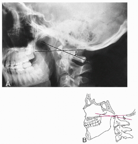
Figure 2-13 METHOD OF BULL. A and B. See text. The posterior angle is measured (double-headed arrow).
George's Line
Synonyms.
Posterior vertebral alignment line, posterior body line.
Technique
Projection.
Lateral cervical spine.
Landmarks.
The posterior vertebral body surfaces are connected with a continuous line that traverses the intervertebral disc. A straight line cannot be drawn because of the normal concavity of the posterior surface. The key landmarks are the alignment of the superior and inferior posterior body corners. (Fig. 2-14)
Normal Measurements.
Normally, there is a smooth vertical alignment of each posterior body corner.
Special Considerations.
Flexion and extension films are especially useful in determining disruptions in George's line. (8,9) The posterior body line can be incorporated with other complex measuring systems to assess stability. (10,11) Care should be taken to eliminate positional rotation, because this will create a projectional disruption of the line at consecutive levels (stair stepping). This line can be applied throughout the entire spine.
Significance.
In 1919 George called attention to the relevance of ascertaining alignment to detect post-traumatic cervical injuries. (12,13) Proper alignment of the posterior vertebral bodies signified no fracture, dislocation, or ligamentous laxity. In burst fractures of the vertebral body, a posteriorly displaced fragment of bone will lie behind the line. (14,15) If an anterolisthesis or retrolisthesis is present, this may be a radiologic sign of instability caused by fracture, dislocation, ligamentous laxity, or degenerative joint disease.
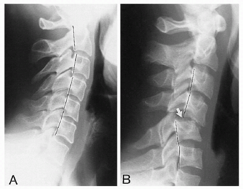
Figure 2-14 GEORGE'S LINE. A. Normal Line. See text. B. Abnormal Line. The abnormality is the result of traumatic bilateral facet dislocation (arrow).
Posterior Cervical Line
Synonyms.
Spinolaminar junction line, arch-body line.
Technique
Projection.
Lateral cervical spine (neutral, flexion, extension).
Landmarks.
The cortical white line of the spinolaminar junction is first identified at each level C1 to C7. Each spinolaminar junction will be curved slightly anteriorly from superior to inferior. For consistency, the most anterior part of the convexity is compared between levels. (Fig. 2-15)
Normal Measurements.
When each spinolaminar junction point is joined, a smooth arc-like curve results. At the C2 level, the spinolaminar junction line in children should not be > 2 mm anterior to this line.
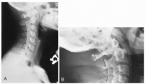
Figure 2-15 POSTERIOR CERVICAL LINE. A. Normal Line. See text. B. Abnormal Line. The abnormality is caused by posterior displacement of the atlas secondary to os odontoideum.
Special Considerations.
None.
Significance.
If the drawn curve is discontinuous at any level, then an anterior or posterior displacement may be present. This line is especially useful for detecting subtle odontoid fractures and atlantoaxial subluxation (anterior), which otherwise may be easily overlooked. (16) A disruption in the middle to lower cervical spine may also be a sign of anterolisthesis, retrolisthesis, or frank dislocation.
Sagittal Dimension of the Cervical Spinal Canal
Technique
Projection.
Lateral cervical (neutral, flexion, extension).
Landmarks.
The sagittal diameter is measured from the posterior surface of the midvertebral body to the nearest surface of the same segmental spinolaminar junction line. (17) (Fig. 2-16)
Normal Measurements.
Measurements vary according to the cervical level. (18) (Table 2-7) Values will be altered in children. (17,19)
| Table 2-7 Normal Sagittal Diameters for the Cervical Spine | ||||||||||||||||||||||||||||||||
|---|---|---|---|---|---|---|---|---|---|---|---|---|---|---|---|---|---|---|---|---|---|---|---|---|---|---|---|---|---|---|---|---|
|
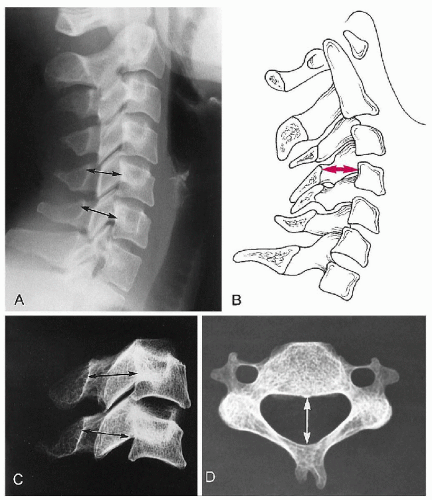
Figure 2-16 CERVICAL SPINAL CANAL. A and B. Sagittal Dimensions. The dimensions at two levels are shown (arrows). See text. C and D. Dry Specimens. Specimen correlation demonstrating the distance being evaluated (arrows).
Special Considerations.
None.
Significance.
Narrowing of the canal (stenosis) may be present when the measurement is < 12 mm, which can be assessed on plain film, CT, and MRI. (20) If degenerative posterior osteophytes are present, the measurement can be made from their tip to examine the magnitude of the stenotic effect. The degree of stenosis from these spurs is best measured on extension films. (18) An abnormally widened canal may be associated with a spinal cord neoplasm or syringomyelia.
The most accurate measurement is by the ratio of the sagittal dimension of the canal and vertebral body (canal to body ratio, Pavlov's ratio). (21,22) A ratio of less than 0.82 is significant for spinal stenosis. (21) The benefit of this method is that it removes the effects of radiographic magnification.
Atlantoaxial Alignment
Synonyms.
Spread of the atlas.
Technique
Projection.
AP open mouth; cervical spine.
Landmarks.
The lateral margins of the atlas lateral masses are compared to the opposing lateral corner of the axis articular surface. (Fig. 2-17)
Normal Measurements.
These two landmarks should be in vertical alignment.
Special Considerations.
None.
Significance.
If the lateral margin of the atlas lateral mass lies lateral to the lateral axis margin, this may be a radiologic sign of Jefferson's fracture, odontoid fracture, alar ligament instability, or rotatory atlantoaxial subluxation. (23,24) If there is overhang of the lateral mass in combination with a laterally tilted dens of > 5°, there is at least a 70% probability a fracture of the odontoid is present. (25) In children up to 4 years of age, overhang of the atlas may be a normal variant resulting from accelerated growth of the atlas (pseudo-spread). (24,26)
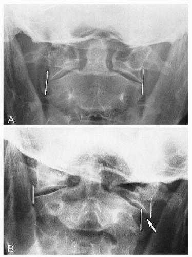
Figure 2-17 ATLANTOAXIAL ALIGNMENT. A. Normal Alignment. B. Abnormal Alignment. The abnormality (arrow) is the result of a Jefferson's fracture of the atlas.
Cervical Gravity Line
Technique
Projection.
Lateral cervical spine (neutral).
Landmarks.
A vertical line is drawn through the apex of the odontoid process. (27) (Fig. 2-18)
Normal Measurements.
This line should pass through the C7 body.
Special Considerations.
None.
Significance.
The line allows a gross assessment of where the gravitational stresses are acting at the cervicothoracic junction.
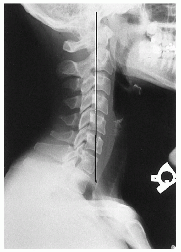
Figure 2-18 CERVICAL GRAVITY LINE. See text.
Cervical Lordosis
Synonyms.
Angle of the cervical curve, cervical (lordotic) angle.
Technique
Projection.
Cervical spine, neutral.
Landmarks.
Numerous methods have been devised. (28,29,30,31,32,33,34,35) Some are described here.
-
Depth of cervical curve. A line is drawn from the superior posterior aspect of the odontoid to the posterior inferior corner of C7. The greatest transverse distance between this line and the posterior vertebral bodies is measured. (32) (Fig. 2-19A)
-
Method of Jochumsen. A line is drawn from the anterior border of the atlas anterior tubercle to the anterosuperior corner of the C7 body. The distance from this line to the anterior border of the C5 body is then measured. (33) (Fig. 2-19B)
-
Angle of cervical curve. Two lines are drawn, one through and parallel to the inferior endplate of the C7 body and the other through the midpoints of the anterior and posterior tubercles of the atlas (atlas plane line). Perpendiculars are then constructed to the point of intersection; the resultant angle is measured. (34) (Fig. 2-19C)
-
Method of Gore. A line is drawn through the posterior surface of the C2 body and another through the posterior surface of the C7 body. The angle formed by these two lines is measured. (28)
-
Method of Drexler. This is a laborious but accurate method. Each individual segment is assessed by drawing lines along the body endplates and measuring the resultant angle. The lordosis value is the cumulative total of each intersegmental measurement. (35)
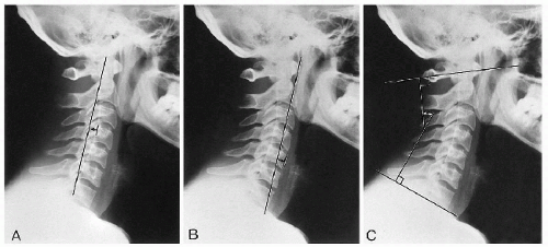
Figure 2-19 CERVICAL LORDOSIS. A. Depth Measurement. B. Method of Jochumsen. C. Angle of the Cervical Curve. See text. Areas of measurement are shown (double-headed arrows).
Normal Measurements.
See Table 2-8.
| Table 2-8 Normal Values for Cervical Lordosis | ||||||||||||||||||||
|---|---|---|---|---|---|---|---|---|---|---|---|---|---|---|---|---|---|---|---|---|
|
Special Considerations.
The position of the head is a critical factor in determining the lordosis. If the chin is lowered, tucked downward, or retracted 1 inch, the effect is to straighten the lordosis. (36,37,38)
Significance.
Many authors have stressed the lack of correlation between altered cervical curvature and clinical symptomatology and its limitations as a prognostic indicator. (31,39) However, a reduced or reversed curve may be observed following trauma, muscle spasm, and degenerative spondylosis. (31,32,36,37,40) In patients with myelopathy caused by degenerative stenosis, response to laminectomy is diminished when the lordosis is reversed or straightened. (41)
Stress Lines of the Cervical Spine
Synonyms.
Ruth Jackson's lines.
Technique
Projection.
Lateral cervical spine (flexion, extension).
Landmarks.
Two lines are constructed on each film. The first line is drawn along the posterior surface of the axis. The second line is drawn along the posterior surface of the C7 body until it intersects the axis line. (40) (Fig. 2-20)
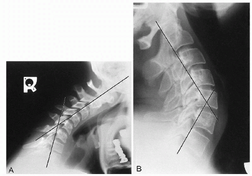
Figure 2-20 CERVICAL STRESS LINES. A. Flexion. See text. B. Extension. See text.
Normal Measurements
-
Flexion. These lines normally should intersect at the level of the C5-C6 disc or facet joints.
-
Extension. These lines normally should intersect at the level of the C4-C5 disc or facet joints.
Special Considerations.
None.
Significance.
The value of these lines has not been established. The intersection point represents the focus of stress when the cervical spine is placed in the respective positions. (40) The point of intersection does not appear to correlate with the level of degenerative disc disease. (42) Muscle spasm, joint fixation, and disc degeneration may alter the stress point.
Prevertebral Soft Tissues
Synonyms.
Retropharyngeal interspace (RPI), retrolaryngeal interspace (RLI), retrotracheal interspace space (RTI).
Technique
Projection.
Lateral cervical spine (neutral, flexion, extension).
Landmarks.
The soft tissue in front of the vertebral bodies and behind the air shadow of the pharynx, larynx, and trachea is measured. The bony landmarks are the anterior arch of the atlas; the inferior corners of the axis and C3; the superior corner of C4; and the inferior corners of C5, C6, and C7. (43,44) At C2-C3 this is called the RPI; behind the larynx, the RLI (C4-C5); and behind the trachea (C5-C7), the RTI. (Fig. 2-21)
Normal Measurements.
Measurements will vary according to the level being measured and the position of the patient at the time of the exposure. (43,44) (Table 2-9)
| Table 2-9 Normal Values for Cervical Prevertebral Soft Tissues | ||||||||||||||||||||||||||||||||
|---|---|---|---|---|---|---|---|---|---|---|---|---|---|---|---|---|---|---|---|---|---|---|---|---|---|---|---|---|---|---|---|---|
|
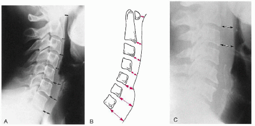
Figure 2-21 PREVERTEBRAL SOFT TISSUE. A and B. Prevertebral Soft Tissues. See text. Areas of measurement are shown (arrows). C. Abnormal Retropharyngeal Soft Tissue Measurement. The abnormality is the result of hematoma formation after cervical trauma (arrows). (Courtesy of Norman W. Kettner, DC, DACBR, St. Louis, Missouri.)
Special Considerations.
The values at the C4 and C5 levels may alter, depending on the position of the larynx, which may change with swallowing, screaming, axial rotation, and lateral flexion. (44) There is no difference between the sexes, and the values are not altered significantly by radiographic magnification. (44) Patients > 180 lb (82 kg) may have a space 1 mm greater than the normal range, and patients older than 70 years have spaces of 1 mm less than normal. (44) No more than a 1-mm change occurs in the measurement between flexion and neutral. (43) Anterior degenerative osteophytes may cause deflection of the pharyngeal contour.
Significance.
Any soft tissue mass may increase these measurements. These include post-traumatic hematoma, retropharyngeal abscess, and neoplasm from the adjacent bone and soft tissue structures.
THORACIC SPINE
Cobb's Method of Scoliosis Evaluation
Synonyms.
Cobb-Lippman method.
Technique
Landmarks
-
End vertebrae. There are two, one each located at the superior and inferior extremes of the scoliosis. They are defined as the last segment that contributes to the spinal curvature. They appear as the last segment at the extreme ends of the scoliosis, where the endplates tilt to the side of the curvature concavity.
-
Endplate lines. On the superior end vertebra, a line is drawn through and parallel to the superior endplate. On the inferior end vertebra, a line is constructed in a similar manner through and parallel to the inferior endplate.
-
Perpendicular lines. At right angles to both endplate lines, lines are drawn to intersect, and their resultant angle is measured. (Fig. 2-22)
Special Considerations.
This is the preferred method in scoliosis assessment. In patients with double scoliotic curves each component should be measured. Care should be taken to ensure that common landmarks are used in progressive evaluations. Interobserver errors in measurement range up to 10°, which is a problem because a 5° progression of a scoliosis between two successive radiographs is considered significant when deciding on therapeutic options. (1,2,3)
Significance.
This procedure was introduced by Lippman in 1935 and later popularized by Cobb. (4) Essentially, curvatures < 20° require no bracing or surgical intervention; however, if curvatures < 20° are present in a patient between 10 and 15 years of age, careful monitoring should be implemented to assess for progression of 5° or more in any 3-month period. (1,5) Curves between 20° and 40° should be braced to prevent progression in the growth period. Surgical intervention may be contemplated for cosmetic reasons, underlying anomaly, curvature progression in an immature spine, or curvature in excess of 40°. (See Chapter 4.)
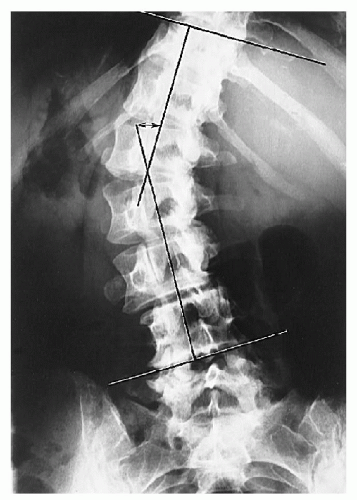
Figure 2-22 COBB'S METHOD OF SCOLIOSIS EVALUATION. See text. The angle measured is shown (double-headed arrow).
Risser-Ferguson Method of Scoliosis Evaluation
Technique
Landmarks
-
End vertebrae. Same as described for Cobb's method.
-
Apical vertebra. This vertebral segment is the most laterally placed in the curve and usually is the most rotated.
-
Vertebral body center. For each end vertebra and apical segment diagonals are drawn from opposing corners of the body to locate the body center.
-
Connecting line. Two lines are constructed connecting the body centers of the apical segment with each end vertebra, and the resultant angle is measured. (Fig. 2-23)
Special Considerations.
This method gives values approximately 25% lower than those of Cobb's method (10°), and some investigators have advocated its use for larger curves; but this practice is to be discouraged. (6) (See Chapter 4.)
Significance.
Ferguson first introduced this methodology in the early 1920s and published his findings in the 1930s and 1940s. (7,8) Like Cobb's method, this assesses the degree of scoliosis and provides data used in the therapeutic decision process.
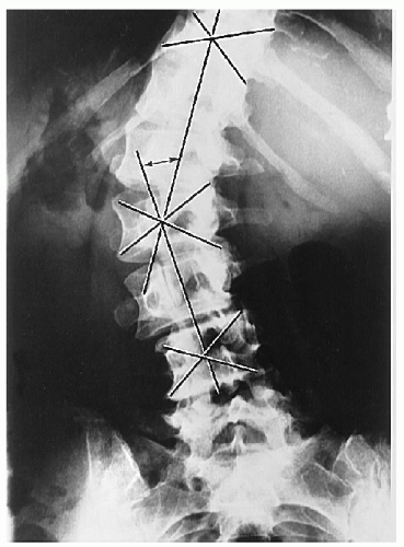
Figure 2-23 RISSER-FERGUSON METHOD OF SCOLIOSIS EVALUATION. See text. The angle measured is shown (double-headed arrow).
Thoracic Kyphosis
Technique
Projection.
Lateral thoracic spine.
Landmarks.
A line is drawn parallel to and through the superior endplate of the T1 body. A similar line is drawn through the inferior endplate of the T12 body. Perpendicular lines to these endplate lines are then constructed, and the resultant angle is measured at the intersection of the lines. (Fig. 2-24)
Normal Measurements.
Measurements vary according to age and sex. (9) (Tables 2-10 and 2-11)
| Table 2-10 Degree of Normal Kyphosis in Females by Age | ||||||||||||||||||||||||||||||||||||||||||||||||||
|---|---|---|---|---|---|---|---|---|---|---|---|---|---|---|---|---|---|---|---|---|---|---|---|---|---|---|---|---|---|---|---|---|---|---|---|---|---|---|---|---|---|---|---|---|---|---|---|---|---|---|
| ||||||||||||||||||||||||||||||||||||||||||||||||||
| Table 2-11 Degree of Normal Kyphosis in Males by Age | ||||||||||||||||||||||||||||||||||||||||||||||||||
|---|---|---|---|---|---|---|---|---|---|---|---|---|---|---|---|---|---|---|---|---|---|---|---|---|---|---|---|---|---|---|---|---|---|---|---|---|---|---|---|---|---|---|---|---|---|---|---|---|---|---|
| ||||||||||||||||||||||||||||||||||||||||||||||||||
Special Considerations.
Frequently the vertebral bodies at the ends of the thoracic spine will not be clearly visible. In these circumstances the first visible segment will suffice but may alter the angular value. Interobserver measurement errors up to 11° are common. (2) Physiologic anterior vertebral body wedging accounts for the natural kyphotic curvature of the thoracic spine. (10,11) This normal anterior wedging for each vertebral body is 4-5° or 2-3 mm. (11,12,13,14) The wedging increases by almost 1 mm for each successive level, with approximately 45° of thoracic kyphosis accounted for by this wedging. (11)
Significance.
The kyphosis may be altered in many disorders. An increased kyphosis may be seen in old age, osteoporosis, Scheuermann's disease, congenital anomalies, muscular paralysis, and even cystic fibrosis. (9,15) The degree of kyphosis increases with age, and the rate of increase is greater in females than in males. (16)
A reduction in the kyphosis (straight back syndrome) may alter the dynamics of intracardiac blood flow and manifest as an apparent cardiac murmur. (17,18)
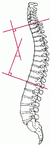
Figure 2-24 THORACIC KYPHOSIS MEASUREMENT. See text.
Thoracic Cage Dimension
Synonyms.
Straight back syndrome evaluation.
Technique
Projection.
Lateral chest.
Landmarks.
The distance between the posterior sternum and the anterior surface of the T8 body is measured. (Fig. 2-25)
Normal Measurements.
The sagittal dimension will normally vary slightly. (18) (Table 2-12)
| Table 2-12 Normal Sagittal Dimensions of the Thoracic Cage | ||||||||||||
|---|---|---|---|---|---|---|---|---|---|---|---|---|
|
Special Considerations.
None.
Significance.
A measured sagittal dimension < 13 cm in males and < 11 cm in females may indicate the presence of the straight back syndrome. (Table 2-13) If an abnormal measurement is found, the chest should be auscultated for a cardiac murmur. If detected, an organic cause should be searched for, although one may not be found. The decreased AP diameter may create such a murmur by creating cardiac compression and altered intracardiac hemodynamics. (17,18)
| Table 2-13 Sagittal Dimensions of the Thoracic Cage in Straight Back Syndrome | ||||||||||||
|---|---|---|---|---|---|---|---|---|---|---|---|---|
|
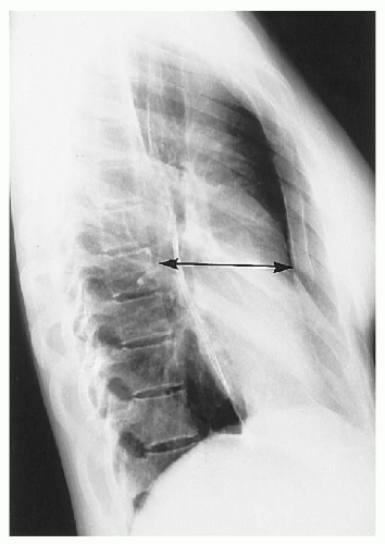
Figure 2-25 SAGITTAL THORACIC CAGE DIMENSION IN STRAIGHT BACK SYNDROME. See text. The dimension measured is shown (double-headed arrow).
LUMBAR SPINE
Intervertebral Disc Height
Technique
Projection.
Lateral lumbar spine.
Landmarks.
A number of methodologies have been described, but only two are presented. (1,2)
-
Hurxthal's method. The distance between the opposing endplates at the midpoint between the anterior and the posterior vertebral body margins is measured. (3) (Fig. 2-26A)
-
Farfan's method. The anterior disc height (A) and posterior disc height (P) are measured and expressed as a ratio to disc diameter (D). These two ratios are then reduced to a ratio of each other. (4) (Fig. 2-26B)
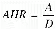
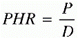
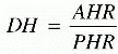
where AHR is anterior height ratio, PHR is posterior height ratio, and DH is disc height.
Normal Measurements.
Considerable variation exists in disc height, according to the lumbar interspace being assessed.
Special Considerations.
When segmental rotation is > 40° or lateral flexion is > 20°, these methods become unreliable.
Significance.
Disc spaces can be altered in many conditions. The most common causes for a decreased disc height are disc degeneration, postsurgery, postchemonucleolysis, infection, and congenital hypoplasia. There is poor correlation between loss of disc height and the focus for low back pain. (2,5)
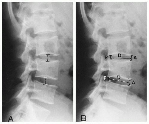
Figure 2-26 INTERVERTEBRAL DISC HEIGHT MEASUREMENT. A. Hurxthal's Method. See text. The areas measured are shown (double-headed arrows). B. Farfan's Method. See text. The areas measured are shown (double-headed arrows).
Lumbar Intervertebral Disc Angles
Technique
Projection.
Lateral lumbar spine.
Landmarks.
Lines are drawn through and parallel to each lumbar body endplate; the lines are extended posteriorly until they intersect. The angles formed at each interspace are then measured. (Fig. 2-27)
Normal Measurements.
Measurements vary according to the lumbar level. (6) (Table 2-14)
| Table 2-14 Normal Values for Lumbar Intervertebral Disc Angles | ||||||||||||
|---|---|---|---|---|---|---|---|---|---|---|---|---|
|
Special Considerations.
An alternative method of measurement includes the vertebral bodies in the calculation. (7)
Significance.
The mean angular values will be altered in conditions of antalgia, muscular imbalance, and improper posture. These measurements may be of assistance in distinguishing the origins of low back pain. In facet syndrome the angles may be increased, whereas in acute discal injuries a reduction in the angle may be seen. (7)
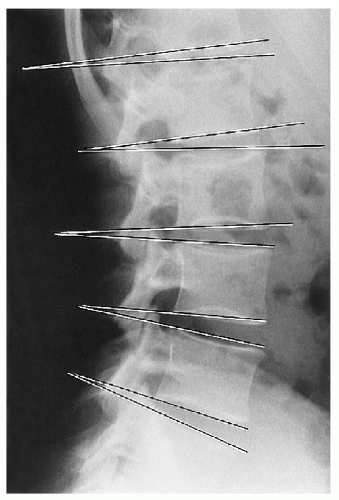
Figure 2-27 LUMBAR INTERVERTEBRAL DISC ANGLES. See text. The angles measured are shown.
Lumbar Lordosis
Synonyms.
Lumbar curve, lumbar spinal angle, lumbar angle.
Technique
Projection.
Lateral lumbar spine.
Landmarks.
A line is drawn through and parallel to the superior endplate of the first lumbar segment. A second line is drawn through the superior endplate of the first sacral segment. Perpendiculars are then created, and the angle at their intersection is measured. (Fig. 2-28)
Normal Measurements.
A wide variation exists within normal individuals. However, the average appears to be 50-60°. (6,7)
Special Considerations.
Some investigators prefer to use the inferior endplate of the L5 body to eliminate the effects of an altered sacral position. (8)
Significance.
The significance of an altered lumbar curve has not been delineated. A wide spectrum of opinions has been expressed, from it being of no importance (9) to it being a prime consideration as it relates to low back pain. (7,10,11,12,13) An increase in lordosis tends to move the nucleus pulposus anteriorly; the significance of this finding is unclear. (14) There is no difference in lordosis between whites and blacks. (15)
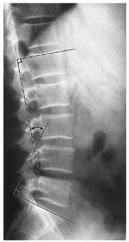
Figure 2-28 LUMBAR LORDOSIS MEASUREMENT. See text. The angle measured is shown (double-headed arrow).
Lumbosacral Lordosis Angle
Technique
Projection.
Lateral lumbar spine.
Landmarks.
Two lines are drawn, and the angle formed is measured. For the first line, the centers of the L3 and L5 bodies are located by intersecting diagonal lines from opposing corners for each of the two vertebra. A line is then constructed joining the midpoints of these two bodies. Next the midpoint of the first sacral segment is located in a similar manner, and a second line is drawn between the L5 and S1 midpoints. The posterior angle thus formed is measured. (Fig. 2-29)
Normal Measurements.
A wide variation in this angle exists. (16) (Table 2-15)
| Table 2-15 Normal Values for Lumbosacral Lordosis | ||||||
|---|---|---|---|---|---|---|
|
Special Considerations.
There appear to be small changes in this angle between the recumbent and the upright positions.
Significance.
The role of an excessive or diminished lumbosacral lordotic angle has not been adequately assessed; however, this is a measurement that can be applied when the upper lumbar segments are not included in the field of study.
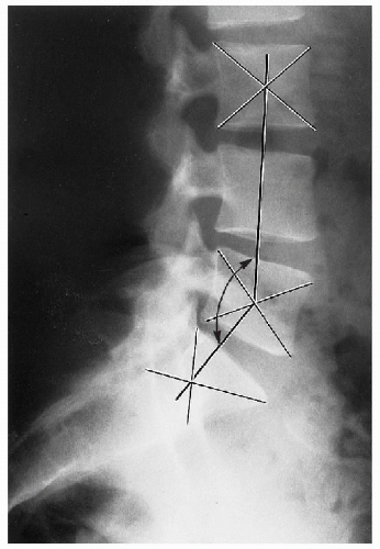
Figure 2-29 LUMBOSACRAL LORDOSIS ANGLE. See text. The angle measured is shown (double-headed arrow).
Sacral Inclination
Synonyms.
Sacral tilt angle.
Technique
Projection.
Lateral sacrum, lumbar spine.
Landmarks.
Two lines are drawn. First, a tangential line is drawn parallel to and through the posterior margin of the first sacral segment. Second, a vertical line is drawn, intersecting the tangential sacral line. The angle formed is then measured. (Fig. 2-30)
Normal Measurements.
A wide variation in this measurement occurs. (16) (Table 2-16)
| Table 2-16 Normal Values for Sacral Inclination | ||||||
|---|---|---|---|---|---|---|
|
Only gold members can continue reading. Log In or Register to continue
Aug 2, 2016 | Posted by in GENERAL RADIOLOGY | Comments Off on Measurements in Skeletal Radiology
How to Draw Mcnabbs Line on Lymbar Xray
Source: https://radiologykey.com/measurements-in-skeletal-radiology/
0 Response to "How to Draw Mcnabbs Line on Lymbar Xray"
Post a Comment